EN EN
EN EN 
 2023-03-14 10:50:54 / Visits: 399
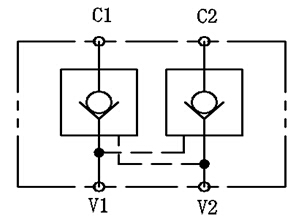
Definition of hydraulic lock:
As the name suggests, a hydraulic lock is a type of "lock" that locks the circuit to prevent the flow of oil in the circuit, as shown in the figure, to ensure that even with a certain external load, the cylinder in the figure can maintain its stationary position.
The specific structure of the hydraulic control one-way valve is a one-way valve with a hydraulic control port. There are valve seats, steel balls, springs, hydraulic control ports, control pistons, and three oil ports A, B, and X.
Application of hydraulic locks:
The hydraulic lock is mainly used to block the static load and can only act as a switch, such as the outrigger of the truck crane, some airport rock climbing vehicles with small load and relatively stable change, horizontal Directional drilling, poor cutting rock climbing vehicles, fire engines, sanitary vehicles and other equipment. It is not suitable for dynamic descent speed control (stable start, descent to avoid stopping) with negative loads and large load changes.
Installation position of hydraulic lock:
Generally speaking, the hydraulic lock must be installed between the throttle and the spool valve (to prevent the closing speed of the hydraulic lock from contracting due to the throttle back pressure), which ensures that the hydraulic lock can quickly lock the actuator and keep it in the position we require to maintain.
Selection of multi valve medium function for hydraulic locking system:
Usually, we recommend that users choose to turn on the intermediate function (Y-shaped intermediate function) of the central multi way valve to reduce the impact of the multi way valve on the hydraulic lock. If it is necessary to use a center closed multi valve (with an O-ring function in the middle position), we recommend that users choose a hydraulic lock on the pilot piston without an O-ring to ensure that when the middle position or multi valve is closed, the pressure on both ends of the pilot piston is equal, thereby preventing the hydraulic lock from opening.
It is worth noting that the pilot piston does not have an O-ring, which will to some extent reduce the opening ratio of the pilot.
The above principle only indicates that based on experience, this principle may sometimes be violated, and hydraulic locks can also smoothly lock hydraulic actuators.
The effect of return oil pressure on pilot opening pressure:
You can refer to the following formula to calculate the return oil pressure opening under hydraulic lock pilot pressure.
PPIL=(..)PCIL/(R-A))+PV
PV is the return oil pressure
Selection of hydraulic lock pilot ratio:
The formula for calculating the pilot pressure required to open the hydraulic lock is as follows:
PPIL=PCIL/(R-A)
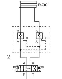
Among them, PPIL is the pilot's opening pressure; PCIL is the maximum load pressure, and R is the pilot ratio; A is the ratio of the area of the pilot cylinder pressure action chamber to the area of the charging action chamber.
In the hydraulic lock system, the area ratio of cylinder A is always less than 1, and the pilot ratio of the hydraulic lock is usually 4:1/7:1, so (R-A) is always positive. The hydraulic lock system shown in Figure 2 on the left has an area ratio of A cylinder greater than 1, where (R-A) may be positive/negative. Therefore, we need to consider selecting the most suitable hydraulic lock based on the area ratio of A cylinder to open the pilot ratio R. Otherwise, the hydraulic lock cannot be opened, and the pressure continues to increase, causing the cylinder to lock.
Huai'an Boster Hydraulic Machinery Co., Ltd
Address:No. 8 Jiaotong Road, Chengbei Industrial Park, Huaiyin District, Huai'an City, Jiangsu Province
Phone:18662981677
Fax:0731-88886666
E-mail:admin@pbootcms.com

Scan and follow us
 CN
CN ES
ES PT
PT SV
SV DE
DE TR
TR FR
FR AR
AR NL
NL FI
FI KO
KO PL
PL RU
RU ID
ID VI
VI