 EN
EN  EN
EN  2023-04-17 09:58:19 / Visits: 488
In daily sales work, Huiming's editor often encounters customers who have just come into contact with hydraulic systems and do not know what the original hydraulic diagram is, but can express functions. Huiming will assist in designing hydraulic schematic diagrams through user expressions. With the widespread application of hydraulic system products, it is also important to learn to read the schematic diagram of the hydraulic system while mastering the basic operation of the system. However, for many people, this is not easy, such as pipelines, valves, and control components..... Wow, there's a lot of things, so isn't there a relatively easy way? The answer is no, today, the editor of Huiming will share with you a good article on how to solve the hydraulic schematic diagram in three steps.

1.We must master basic theoretical knowledge.
Learn more and learn the latest hydraulic theory knowledge, without detailed introduction here. There is a lot of information in the market, and everyone can purchase and learn according to their needs.
2. We must have rich practical experience.
Based on the theoretical knowledge learned and combined with the actual situation on site, differences with the data are discovered, and hydraulic principles, including the working principle of the equipment, are analyzed for targeting. Then, after multiple exercises, specific hydraulic systems can be cooked.

3. Identify graphic symbols
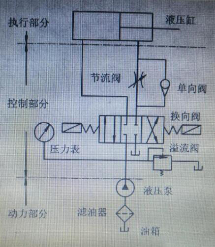
3.1. The components of hydraulic system graphical symbols that constitute hydraulic graphical symbols are points, lines, circles, semicircles, triangles, squares, rectangles, capsules, etc. This point represents the connection point of the pipeline, which means that the internal flow channels of two pipelines or valve plates are connected to each other; The solid line represents the main pipe of the oil pipeline; The dashed line refers to the control of road pipelines; The internal frame of the marked points indicates that multiple valves are installed in a single integrated block, or some valves are installed in the pump to control the pump. The large circle plus a small solid triangle represents a hydraulic pump or hydraulic motor (with two triangles facing opposite directions), the middle circle represents a measuring instrument, and the small circle is used to form a one-way valve element with a rotary joint, mechanical hinge, or roller, A semicircle is a component of a hydraulic motor that limits the rotation angle or swing of a hydraulic cylinder; A square is a component that constitutes a control valve and auxiliary components, such as a valve body, oil filter housing, etc.; The rectangle represents the components of the hydraulic cylinder shell and valve, cylinder piston, and some control method; The middle rectangle represents the fuel tank, and the shape of the bag represents the accumulator and pressure tank.
3.2. The graphical symbols of hydraulic diagram functional components representing functional components are triangles, straight arrows, oblique arrows, bows and arrows, etc.
3.2.1 A solid triangle represents the direction of pressure transmission and indicates that the working medium used is liquid. Pumps, motors, hydraulic valves, and electro-hydraulic valves all have solid triangles with this functional component.
3.2.2 Arrows indicate the path and direction of liquid flow, and arrows added to hydraulic pumps, hydraulic motors, springs, proportional electromagnets, etc. indicate that they are adjustable.
3.2.3 The curved single arrow and bidirectional arrow indicate the direction of rotation of the engine hydraulic pump hydraulic motor, the bidirectional arrow indicates that they can rotate forward and backward, and other arrows such as "W" indicate springs, etc.

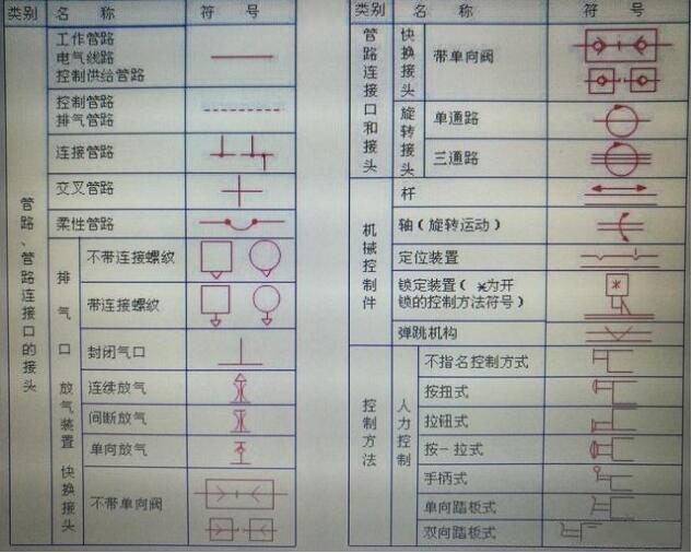
3.3 Other symbols: pipeline and pipe fitting connection symbols, mechanical control and control mode symbols, pump and engine graphical symbols, hydraulic cylinder graphical symbols, various control valves (such as pressure valves, flow valves, steering valves, etc.) graphical symbols, various auxiliary components graphical symbols, detectors or indicators graphical symbols, etc.
In short, by learning theoretical knowledge and applying it in practical work, we can gain a faster understanding of hydraulic systems. Using hydraulic solutions can effectively communicate with our hydraulic supplier Huiming, accurately complete product functions and other parameters, and achieve dual benefits.
